SpaTools: ShrinkWrap - A tool to create Concave Polygon
Relationships in all environments have boundaries
which are generally acceptable limits usually set for permissible behavior to a
specific relation. The flexibility of a boundary varies
with the relationship…formal relationships have a very rigid boundary and
cordial relationships (family and friends) cling-on very softly.
TIN (Triangulated Irregular Network) is a
relationship known in the GIS or CAD environment developed from survey data
points. Workflows in these environments take an optional input of “Boundary” to
limit outputs for the extents of a surface. AutoCAD Civil 3D, BricsCAD or any
other CAD package is used in the CAD environment whereas ArcGIS 3d Analyst,
QGIS or any other GIS software are tools in the GIS environment. The surface
generated from TIN is then utilized to create contours, volumetric computations
(Cut/Fill) and other processes.
The “Boundary” refines such processes for a
surface in the TIN. It is created by connecting exterior data points forming a
polygon. I started to write blogs on AutoCAD with a prefix of SpaToolsto
introduce a set of tools. The first blog of this series was based on a
condition that:
"Every
point in the input point set is vertex of resulting polygon".
(See the first SpaTool
to “Construct polygon /
Polylines from a set of points”).
This
SpaTool works well when extents of boundary properties, houses or lakes etc are
required to be constructed from survey data points. The algorithm is unique and
based on an idea from the Land Record System of Sindh, Pakistan. (Up-coming
Blog).
However,
the formal (default) setup for a “Boundary” is always a “Convex Hull”. The “Convex
Hull”is a polygon with the shortest perimeter to enclose a set of points, such
that:
- All the interior angles are less than 180 resulting all the vertices points outwards, away from the center.
- A line drawn through a convex polygon will intersect the polygon exactly twice.
- The diagonals of a convex polygon lie entirely inside the polygon.
Various algorithms are proposed for
constructing the “Convex Hull”of a finite set of points with varying
complexities and can be found under the subject of “Computational
Geometry”. I have implemented the well-known“Grahm Scan Convex Hull” algorithm.(See
the SpaTool to "Construct Convex Hull from set of Points").
This blog aims at describing the informal
flexibility which can “ShrinkWrap” the “Convex Hull” cordially to the spread of
a point data set in the TIN. But first, let us have a recap of the properties
of a non-convex, i.e. a concave polygon:
- A polygon that has one or more interior angles greater than 180° resulting some vertices point 'inwards', towards the center.
- It looks sort of like a vertex has been 'pushed in' towards the inside of the polygon.
- A line drawn through a concave polygon can intersect the polygon in more than two places.
- Some of the diagonals of a concave polygon will lie outside the polygon.
- Regular Polygons are never concave by definition.
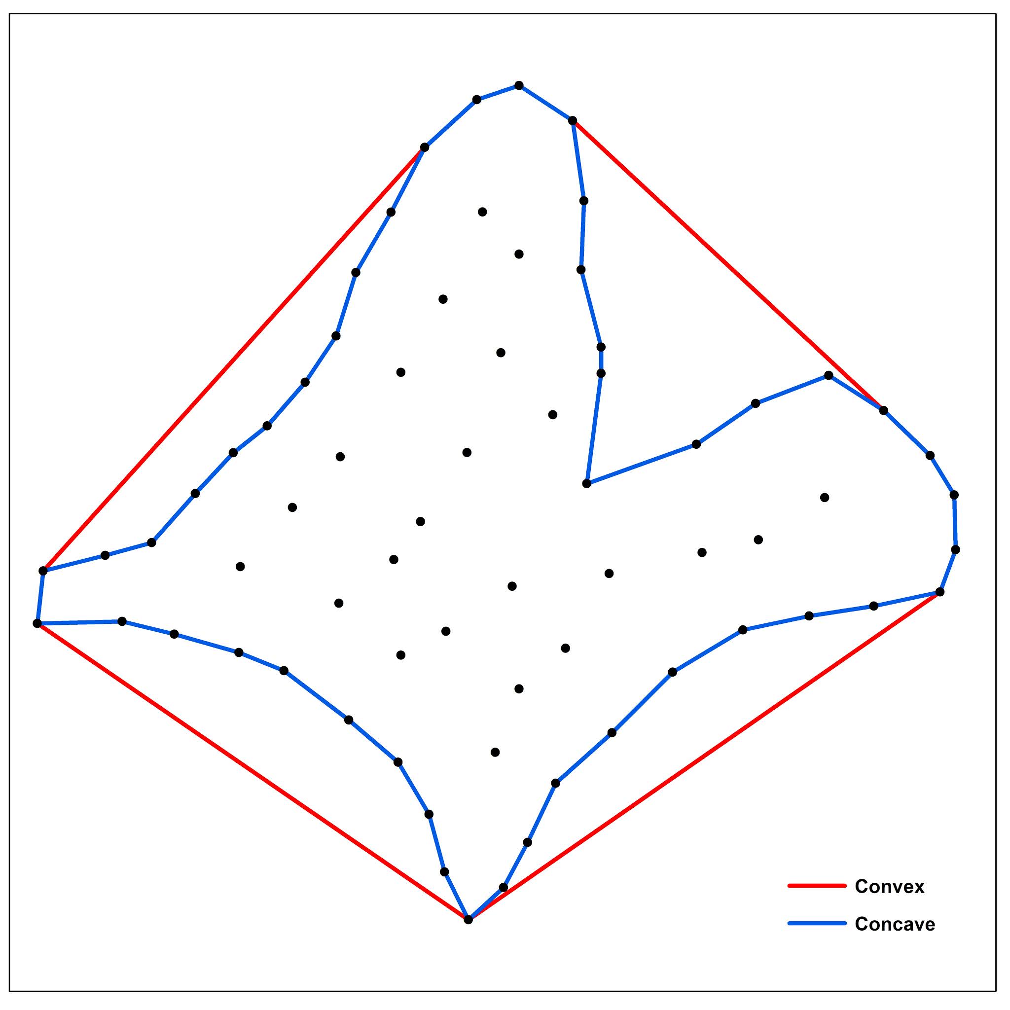
The difference between Convex and Concave polygon
around a cluster of points is illustrated below:
It might be noted that, we will always have ONE solution / output of a convex polygon for
the same set of points regardless of the type of algorithm used.
But, for the same set of points we may have
different outputs of concave polygons as illustrated below:

From the illustrations above, it can be seen
that convex edges of the convex hull can be concaved towards the center of the “Convex
Hull” polygon to produce a concave polygon.
But what is the limit for this concavity? …
This is my point of interest.
Leaving aside this “Concavity Index” for the time being, let’s focus on the conditions to be satisfied.After all the algorithm must converge in a finite time with a valid solution;
The resulting polygon must have vertices from the input set of points.
All the other points must lie inside the resulting polygon.
The polygon should NOT be self intersecting.
If “Convex Hull” is a polygon with Zero
Concavity Index (CI = 0), then we can say that a concave polygon will have
greater than Zero Concave Index (CI) … the most concave polygon will be with the
highest concavity index, i.e.Unity (One).
Based on these conditions and assumptions, I
formulated an algorithm and implemented it using the AutoCAD .Net API. It is
now included as part of the SpaTools.
It takes two inputs:
- Finite set of 2D points (AutoCAD point objects).
- A concavity index (From Zero to One)
The Zero CI (Concavity Index) will alwaysresult
in a “Convex Hull”. While a CI of Unity (One) will construct the most concave
polygon introducing noses and ears. The points can be selected on screen and
the CI value can be chosen by moving a slider towards left or right as depicted
below:

Here
is a demo of the latest SpaTool when applied on a point data set with different
CI values.
 |
| Polygon with Zero CI resulting in a Convex Polygon |
 |
| Polygon with 0.5 CI resulting in a Concave Polygon |
 |
| Polygon with 0.75 CI resulting in a Concave Polygon |
 |
| Polygon with 0.8 CI resulting in a Concave Polygon |
"LINEWORKSHRINKWRAP"
is an existing command in AutoCAD Civil 3D which runs only on the lines,
polylines and other linear objects. However, to create a confined boundary
around points, I couldn’t find anything in AutoCAD or BricsCAD … :)
This
addition to SpaTool was certainly useful for me when a confined boundary around
the points was required for surface modeling.
Download
the new SpaTool and use it on different sets of points with different Concavity
Index values. Your feedback and comments are always welcome.


Comments
Post a Comment