انجنئیرنگ کا ملاکھڑہ
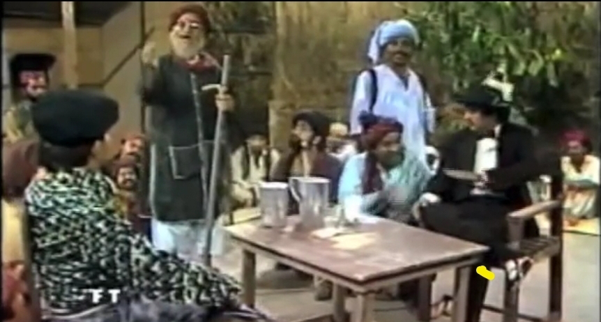
مشہور ڈرامہ نگار اور مصنف عبدالقادر جونیجو کے مشہور ڈرامہ "چھوٹی سی دنیا" میں انگریزی بولی کا ملاکھڑہ یاد آگیا جس میں جانو جرمن اور مراد علی خان صاحب مد مقابل تھے۔ پی آی سی پاکستان انجینئرنگ کونسل کی الیکشن کی مہم میں لاتعداد مختلف امیدواروں کی طرف سے رکارڈیڈ فون کالز، واٹس ایپ میسیج اور TV پر الیکشن کمپین دیکھتے ہوئے ایسے لگ رہا ہے جیسے کوئی ملاکھڑا ہونے جا رہا ہے ۔ "انجنیئرنگ کا ملاکھڑہ" ۔۔۔ ملاکھڑہ سندھی لفظ ہے جس کا مطلب مقابلہ جو عمومی طور پر دو پہلوانوں کے درمیان اکھاڑے میں ہوتا ہے۔ کسی یونیورسٹی کا وائس چانسلر اگر پی آی سی پاکستان انجینئرنگ کونسل کا عہدیدار ہوگا تو یہ دونوں عہدوں کے ساتھ زیادتی ہوگی۔ واپڈا کا رٹائرڈ چیئرمین اگر پاکستان انجینئرنگ کونسل کا عہدیدار بنے گا تو یہ انگریز کے بنائے ہوئے رٹائرمنٹ والے قانون کی خلاف ورزی ہوگی۔ کنسلٹنٹ کمپنی کا مالک اگر پاکستان انجینئرنگ کونسل کا چیئرمین بنکے اگر انجنیئرز کی فلاح و ترقی کے لیے کام کر بھی لے گا تو وہ اپنی کمپنی ڈبودے گا۔ یونیورسٹی کا پروفیسر اگر اپنے اسٹوڈنٹس سے زیادہ پاکستان ا...