SpaTools: Extract Topographic Profile From Contours In AutoCAD
A topographic map is simply the two dimensional representation of a portion of three dimensional surface of earth. Topographic maps provide the detailed information about the natural and man-made aspects of the terrain, but are best known for their series of contour lines that show elevation changes, and colors signifying varying land types and bodies of water. Contour lines are used to determine elevations and are lines on a map that are produced from connecting points of equal elevation (elevation refers to height in feet, or meters, above sea level). By reading contour lines, one can measure the steepness of a hill, the height of a mountain, and even the depth of a lake or Ocean. The contours can be generated by a DEM (Digital Elevation Model), TIN (Triangular Irregular Network) or a surface using different software such as ArcGIS.
Most of the topographic maps used for planning and detailed design in construction and engineering industry for roads, sewers, pipeline, railway lines, dams, irrigation structures & canals, urban planning and geological studies are in AutoCAD format. Engineers, architects, geologists and designers often need topographic profiles to understand and analyze the topographic relief. Topographic profile is obtained by cutting transversely the contours of a topographic map.
A topographic profile is a two-dimensional cross sectional view of the landscape. It provides a side view of the relief of the terrain along a line drawn between two locations on a topographic map.
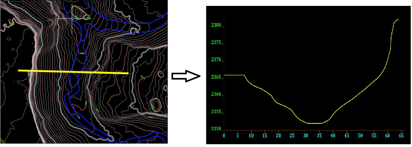
A new tool is added to SpaTools to extract topographic elevation profile from contours. The command can be executed by EXTRACTPROFILE command.

As soon as EXTRACTPROFILE Command is entered, it will ask to draw a line along which the profile is required to be sliced. A dialogue box will appear on the screen.

The profile length in drawing units will be shown at top. Topographic map may contain many layers besides contour layers. In order to extract profile from Contours, User has to select the Contour Layers from the list. Clicking on the layer names on list will select or deselect the layers.

On the right side, there is a settings panel. These settings control the appearance and presentation of the elevation profile to be drawn.

Vertical ExaggerationIn some cases topographic relief of the terrain is modest, such as the case of small hills and other subtle features as opposed to mountainous terrain, or the profile of interest is extended over a large horizontal distance relative to vertical relief. In such situations the elevation profile may only show small variations in elevation without much detail of the topography. For this reason some amount of vertical exaggeration is used in order to get a clearer picture of the subtle changes in topography and emphasize vertical relief and slope steepness. The default value is 1 (one) which will not exaggerate the elevation values. Any positive non-zero value is a valid input to Vertical Exaggeration.
Vertical Scale Tick Interval
This setting will control the vertical scale ticks and labels on the left side of the extracted profile. Vertical Scale Tick Interval settings to 2 (two) will place the vertical scale ticks at every two vertical units with labels as shown in following figure (Green labels):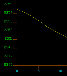

Horizontal Scale Tick Interval:
This is the same setting as Vertical Scale Tick Interval but for horizontal distance. User can specify the horizontal tick and label interval settings by entering any positive non-zero number. The Horizontal Scale Tick Interval of 5 units will produce the output as shown in above figure (Cyan labels).
Draw Elevation Labels & Draw Distance Labels:
If Draw Elevation Labels checkbox is checked, the program will place the elevation labels below the horizontal scale bar. Similarly, if Draw Distance Labels checkbox is checked, the program will place the distances along the profile line for associated extracted elevation labels below horizontal scale bar as shown in following figure (Red labels).

Export Data to CSV:
The data extracted for profile can be exported into CSV (Comma delimited file) by checking the Export Data to CSV checkbox. The user has to browse the path and name of the output CSV file.

The updated SpaTools DLL can be downloaded from Cadomation.
Give your feedback and suggestions for new tools in comments.
To get more updates about SpaTools, subscribe by email.
Note: Read the previous blog if there is any error in loading using Netload.


Unknown command "EXTRACTPROFILE". Press F1 for help.
ReplyDeleteAkramRafi
You must UNBLOCK the downloaded DLL first as mentioned in the first blog of SpaTools.
DeleteAutocad not executing "extractprofile" command
DeleteUnblocking dll file...didnt helped it executing
DeleteRDM COMMAND NOT MARKED END RD PLEASE CHECKIT
ReplyDeleteI have check unblock but still "Unknown command "EXTRACTPROFILE". Press F1 for help."
ReplyDeletethanks extractprofile command now run properly
ReplyDeleteThank you Sir for sharing such a nice tool. It works great for a single line. What if the profile for a polyline can be generated selected on screen ?
ReplyDeleteCan you update it to extract profile along a polyline?
Hi, I tried to use this plugin to create a profile of a surface. The surface i used is one of the civil 3d 2021 tutorials called Profile 2-B. I drew a polyline and then followed the instructions above but i received an error message saying
ReplyDelete"Index was out of range. Must be non negative and less than the size of the collection. Parameter name: index."
In the details section is says
"************** JIT Debugging **************
Application does not support Windows Forms just-in-time (JIT)
debugging. Contact the application author for more
information."
Can you help me please?
Thanks for your feedback.
DeleteCan you send the drawing to info@cadomation.com to resolve and rectify the bug?